
Lexical analysis or scanning is the process of reading the stream of characters comprising the source code of a program. The scanner groups the characters into sequences called lexemes. For each lexeme, the scanner produces tokens as output. The scanner also removes comments, whitespace, handles numbers, recognizes reserved words and identifiers.
Syntax analysis or parsing takes each token produced by the scanner and creates a tree-like intermediate representation that depicts the grammatical structure of the token stream. The syntax of a programming language is typically specified by context-free grammars or Backus-Naur Form (BNF) notation. The parser verifies that the string of tokens (syntax) is correct and reports any syntactical errors.
A symbol table is a data structure that records variable names, associates values, or attributes, with each token generated by the scanner. The symbol table is a necessary component of most all compilers and provides access to critical information about each identifier as it is processed. Symbol table implementation can be done using unordered lists, ordered lists, binary search trees, or hash tables.
The semantic analyzer uses the syntax tree and the information in the symbol table to check the source code for proper semantic consistency. Additionally, it gathers type information and saves it in the symbol table for subsequent use during intermediate code generation. One of the more important functions of semantic analysis is type checking. Type checking ensures that operators have matching operands so that attempts to add a number to a string are flagged as errors.
Many compilers generate an explicit low-level intermediate representation of the source code. That is, the intermediate code generator produces a kind of pseudo code (p-code) representation rather than actual machine code so that it can be easily developed into code for a specified machine.
Code optimization is accomplished using algorithms and heuristics to improve the code generated by intermediate code generator. However, very few optimizing compilers generate truly optimal code. There are several reasons for this but suffice it to say that every compiler reaches a point of diminishing returns for the time invested in optimizing code. Sometimes, when a section of code is used only once or at most very rarely, optimization may be superfluous.
The code generator takes the intermediate representation as input and translates it into either machine code for the targeted microprocessor, or it produces assembly language mnemonics for an assembler program. The code generator is responsible for memory and register allocation, stack utilization, and variable assignments.
Compilers are fundamental to computer programming. They translate human-oriented programming languages into machine code used by microprocessors.
Compilers allow the machine-dependent details of a program to be ignored so programmers can focus on writing applications that solve real-world problems. Modern compilers tend to be very sophisticated software applications; however, simple, nontrivial compilers can be designed and written by anyone with an interest in exploring compiler technologies.
Compiler design and development is an exercise in engineering design. The process of writing a compiler is a very complex ordeal, but a rewarding undertaking. Compiler writers have great latitude and influence over not just the compilers they write, but all the programs that their compilers compile. This is the rewarding aspect of writing a compiler. It is also what makes compiler design and development extremely challenging.
This manual uses an applied approach to writing a compiler rather than dwelling on academic theory. It incorporates well-developed principles from scanning and parsing to intermediate and final code generation.
It allows users to:

Craft the Ada/PM Compiler
This applied approach to designing and developing a 64-bit compiler focuses on practical skills rather than academic theory. Designed for the practicing programmer who wants to learn to write a compiler for a reformed language, this manual teaches you what you need to know to get started. Excerpts in the accompanying manual are taken from the book, Ada/PM Compiler Design & Development, First Edition.
NOTE Ada/PM Compiler Design & Development and accompanying manuals and help files are currently undergoing editing and testing. Thank you for your patience.
A compiler is a program that converts the source code for a programming language into machine code for a target microprocessor. Compilers generally consist of a scanner that performs lexical analysis, parser that performs syntax and semantic analysis, intermediate code generator, code optimizer, low-level code generator, and symbol table.
If you have the desire to create a compiler, this publication is aimed at you. It does not matter whether you are a hobby programmer, student, or a professional developer. The approach is the same for everybody.
A compiler is a program that takes code written in a high-level source language and translates it into a low-level language, usually assembly or machine code. Generally, low-level code is targeted to a family of microprocessors. The compiler covered in this manual is specifically designed to work with Intel x86-64 and AMD64 processors.
The front-end of a compiler consists of a scanner, parser, symbol table, and intermediate code generator. The scanner reads the source code character by character and constructs tokens out of the basic elements (lexemes) of the source input stream. This process is called lexical analysis and begins the process of developing one or more symbol tables. It also begins one of the most important functions of a compiler, error detection and reporting.
The parser conducts syntax and semantic analyses on the tokens and produces a series of parse trees based on the set of grammar rules characterizing the correct form of sentences in the language. It also detects errors and reports them as they occur.
The symbol table contains information about identifiers such as type, location in memory, limitations, and other data needed by the parser. The symbol table and parse trees are used to produce intermediate code.
The back end of a compiler consists of a code optimizer and code generator. The optimizer uses various strategies to improve the speed and space requirements of generated code. The code generator then converts the optimized intermediate code into assembly instructions that are passed to an assembler, or directly into machine-level instructions that can be read directly by the microprocessor.
An integral part of specifying an operational compiler is coming to grips with its actual internal workings. This requires familiarity with the following concepts:
In 1984 Gehani wrote, "Most programmers adhere to the old-fashioned view that the purpose of programs is to instruct our machines, whereas modern programmers know that the purpose of our machines is to execute our programs." (Gehani, N., 1984, Comparing and Assessing Programming Languages, Englewood Cliffs, NJ, Prentice-Hall.
Compiler. A language is only as good as its compiler. Therefore, a compiler must be totally reliable, which means it always must do what the programmer intended. This requires every program to be checked against every single rule of the language so that no incorrectly formed code can be compiled without warning the programmer. It also means all instructions are correctly translated into machine-level form so that no incorrect code can be allowed to cause a program to crash unintentionally. There are other important qualities that a well-designed compiler should possess.
A compiler must:
The compiler is composed of the following component parts:
Programming Language. The programming language described in this document is called Ada/PM. Ada/PM is a specialized language incorporating many of the best features found in modern renditions of languages like Ada 2012, Pascal, Modula-3 and Oberon. It is a bi-level programming language designed primarily with readability and reliability in mind. Bi-level means that it contains both high-level programming structures and low-level access to the microprocessor using standard assembly language mnemonics. Ada/PM is an imperative programming language focused on placing named data objects into memory locations and then performing operations on them using various subroutines.
The purpose for defining this language is to help users learn how to design and develop a compiler based on a simple to understand, statically verifiable, orthogonal programming language. Secondary purposes include learning how to develop language and compiler specifications, understanding the functionality of the underlying processor, and building support tools like component libraries and source code verification programs.
In my opinion, Ada is an overly large language and its compiler is very complex. BASIC is a good language but lacks structure and abstraction. Although very powerful, C is terse and unsafe for many applications. Modula and Pascal contain good abstraction and safety features but are not expressive enough in terms of hiding implementation details. Spark is a subset of Ada that introduces the concept of programming-by-contract but remains overly complex and proprietary. Go is based on C but lacks constructs to directly access the microprocessor. I decided a fresh language was in order because embarking on this new frontier would prove both challenging and rewarding.
Some of the main features of the Ada/PM compiler include the following:
Note that Ada/PM is not explicitly designed for high integrity applications, embedded device drivers, or general systems developmental domains. Unlike high integrity applications written in Ada and Spark, Ada/PM will halt program execution upon encountering a fatal error, offer corrective actions, and then wait for user input before continuing. This is by design because Ada/PM applications are meant for domains that expect correct data results. It therefore enforces those expectations.
Scanning (lexical analysis) is usually the first phase of a compiler program. Based on finite-state machines, the scanner reads one character at a time from a source file and converts them into recognizable sequences of characters that form the tokens included in the language. Scanners are often called lexers or tokenizers. In programming languages, scanners are generally combined with parsers to analyze the syntax of the language.
The role of the scanner (lexical analyzer) is to read the input source file character by character and group recognized patterns of characters into lexemes and produce as output a sequence of tokens for each lexeme. Note that the difference between the term lexeme and token is that a lexeme is a recognized string pattern such as the reserved word PUT. The scanner turns the lexeme into a token by outputting the name of the identifier as well as associated attribute information such as type, value, location, and scope. Thus, a lexeme represents an object and when paired with its associated attributes, becomes a token.
Note also that the term object means a named entity that is assigned a memory location and a value at that memory location. An object is anything that is assigned memory space and then takes up that memory space with a value.
Regular expressions are a convenient method of specifying certain simple sets of strings. They are used to specify the structure of the tokens used in a programming language. Typically, regular expressions are used in scanner generators.
Regular expressions, also called regular grammars, are a means of specifying certain string patterns called lexemes. We are interested in regular expressions because we will use them to specify the structure of tokens declared in our programming language. In fact, the set of regular expressions used in our scanner are expressly aimed at developing specific recognizers for the Ada/PM programming language.
The regular expressions used in developing the Ada/PM scanner have several desirable properties:
For instance, the regular expression for an Ada/PM identifier is shown in Figure 1.
Figure 1. Regular Expression for an Identifier

letter ::= { ["_"] letter | digit }
The vertical bar above means OR, the curly braces group expressions that can be repeated zero or more times, and the juxtaposition of _letter signifies concatenation.
Notice Figure 1 depicts that an Ada/PM IDENTIFIER must start with a letter (a..z | A..Z). The first letter can be followed by an underscore then at least one letter or digit. In the case of an optional underscore symbol, the underscore must be followed by at least one letter or digit. Brackets [ ] are used in defining a regular expression signify that zero or one (meaning optional) of the symbols contained within the brackets may be used. Parentheses ( ) are used to group symbols. The vertical bar | represents an "OR" operator.
Figure 2 shows legal and illegal Ada/PM identifiers.
Figure 2. Legal and Illegal Identifiers

LEGAL IDENTIFIERS       ILLEGAL IDENTIFIERS
Add_Two_Numbers         Add__Two__Numbers  -- Cannot use two adjacent underscore
P25_Units               25_Units           -- Cannot use a digit as the first character
My_3_Variables          My#3%Variables:    -- Cannot use symbols other than underscores
x_1                     _                  -- Cannot use single stand-alone underscores
Div_by_Two              _Div_by_Two        -- Cannot use an underscore as the first character
Big_Definition          Big_Definition_    -- Cannot use an underscore as the last character
A315_Vectors            A315 Vectors       -- Cannot use spaces within a name
A recognizer for a programming language takes as input a string of one or more characters and determines whether the string is a token of the language. Converting regular expressions to recognizer diagrams is to construct generalized transition diagrams from the expressions. Deterministic Finite Automata (DFA) represent transition diagrams that contain at most one path leaving one state and into the next state. A DFA is a theoretical machine accepting regular languages.
Deterministic Finite Automata (DFA) are used to create finite-state machine-oriented subroutines that deal with the tokens in our programming language. Finite-state machines (FSM) have one purpose: to accept or reject input strings as tokens. Finite automata are often represented as either transition tables or transition diagrams, which use circles and arrows to portray finite-states and transitions, thus its name. Deterministic finite automata always define a unique next state as individual characters making up a token are recognized and processed by the lexical analyzer.
Ada/PM's DFA transition diagrams are designed for use in developing the scanner program. The conversion of the regular expression for identifiers into a DFA diagram is shown in Figure 3.
Figure 3. Finite-State Transition Diagram for Identifiers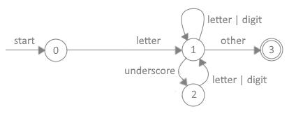
As can be seen in Figure 3, nodes, represented by circles, are called states. Arrows radiating out of each state are called edges. The labels on edges are called transitions. The start state begins at the circle containing a zero. The start point represents the process of reading the first character of a token. If the initial character is an optional underscore or letter, then the scanner knows it is dealing with an identifier and the subroutine jumps to State 1.
For the subroutine to leave State 2, the next character read from the source file must be either a letter or digit. If it is, then the subroutine transitions back to State 1. The subroutine will remain in State 1 if the next group of characters read from the source file are recognized as letters or digits. If an underline is read, then the subroutine jumps to State 2. When any other character is read, for instance a blank space, then the subroutine is done and transitions to the final state, State 3.
In Figure 3, the end state, sometimes called the accepting state, is represented by the number 3 inside double circles. When the subroutine reaches an end state, it knows it has a fully formed lexeme. The arrows pointing to each circle represent transition conditions. The finite-state transition diagram depicted in Example 3 can be converted to program code as shown in Listing 1.
----------------------------------------------------------------------------------------------
-- Listing 1. Program Stub for a DFA Transition Diagram
-- Purpose is to tokenize the input stream from a program's source code
----------------------------------------------------------------------------------------------
token: string [64];                  -- Define a 64-byte buffer named token
chr: char;                           -- Define chr as type char
subtype cnt is integer range 1..64;  -- User defined subtype
count: cnt = 1;                      -- Define count as type cnt with initial value
whitespace: constant char = " ";     -- Define whitespace to be a blank character

<<State_0>>
chr = get_ch(count);                 -- Get character from source
  while chr == whitespace loop       -- Loop if character is whitespace
    count = count + 1;
    chr = get_ch(count);             -- Get next character from source
  end while;                         -- Must have encountered a non-whitespace character
  count = 1;                         -- Reset count

case chr is
  when letter | underline then       -- Start of an identifier
    Get_Identifier();                -- If token is an identifier, get the rest of it
  when others                        -- Statements to check for other kinds of tokens
    Raise_Exception (error_number);
end case;

procedure Get_Identifier () is
begin
  if chr == letter then              -- Determine next transition state
    goto State_1;
  else                               -- Char must be an underline
    goto State_2;
  end if;

<<State_1>>
  token(count) = chr;                -- Store char in token
  count = count + 1;
  chr = get_ch(count);               -- Get next character
  if chr == letter or chr == digit then
    goto State_1;
  elsif chr == underline then
    goto State_2;                    -- Deal with hyphen
   else
    goto State_3;
  end if;

<<State_2>>
  token(count) = chr;                -- Store underline character
  count = count + 1;
  chr = get_ch(count);               -- Get next character
  if chr == letter or chr == digit then
    goto State_1;
  else                               -- An underline must be followed by either a letter or
    Raise_Exception (Error_Number);  -- digit. Also, two underlines cannot be placed together
  end if;                            -- and an identifier must end in either a letter or digit

<<State_3>>
-- Routine to add identifier to symbol table
-- Routine to add identifier to syntax tree
-- Return to State_0 to retrieve next token
end Get_Identifier;
----------------------------------------------------------------------------------------------
In Listing 1, we assumed the first character retrieved from the source line happened to be a letter or underline. This caused the scanner to know it is working with an identifier. Knowing that it is building an identifier, the scanner subroutine passes program control to either State 1 or State 2 to finish retrieving the rest of the token. Notice how State 2 ensures that at least one letter or digit follows an underline and that two underlines cannot be grouped together.
Notice how easy it is to translate a DFA transition diagram into actual program code. Similar transition diagrams exist for other Ada/PM token types including numbers, symbols, end-of-file, end-of-line, comments, strings, and pragmas. Each has its own set of numbered states and transitions to those states.
There are two general approaches to parsing. The first is termed top-down. The second is termed bottom-up. The productions produced by a top-down parsing technique represent a leftmost derivation. Conversely, the productions produced by a bottom-up parsing technique represent a rightmost derivation. When specifying a parsing technique then, one must state whether a leftmost or rightmost parse will be produced.
The purpose of a parser is to collect string information into groupings as specified by production rules, and then output parse trees for the code generator. Parse trees graphically represent the grammar resulting from the choice for replacement order of the production rules.
There are many ways to describe the semantics of a programming language. Most modern compilers generally employ context free grammars (CFG). Grammars are considered context free when their production rules can be applied regardless of the context of a nonterminal. Context free grammar production rules are formulated using the Backus-Naur Form (BNF).
Every programming language has its own set of syntactical rules that provide guidance on how to form correct constructs. Ada/PM employs a Context-Free Grammar (CFG) to specify its syntax. A CFG is a formal methodology represented by a series of production rules containing terminal and nonterminal symbols. Context-free grammars, in the form of extended Backus-Naur Form (BNF) notation, are used by Ada/PM to accept the output of the scanner and verify that the source code satisfies the syntax rules of the language. CFGs provide a simple mathematical representation of the rules by which the output of the scanner are described for use by the parser.
Ada/PM is a context-free grammar. Its syntax consists of rules called productions. As per the ISO/IEC 14977 International Standard, a production rule consists of a meta-identifier (name of the nonterminal symbol being defined) followed by a define-symbol followed by a definitions-list. Ada/PM's BNF does not require a terminator-symbol such as a period at the end of a production.
A definitions-list consists of an ordered list of one or more single-definitions separated from each other by a definition-separator-symbol (::=). A single-definition consists of an ordered list of one or more syntactic-terms separated from each other by a separator-symbol. (See ISO/IEC 14977:1996E, https://www.cl.cam.ac.uk/~mgk25/iso-14977.pdf).
Productions. A BNF grammar is essentially a list of rewrite rules defined as productions in which terminals and nonterminals may be combined to form strings. Productions can be thought of as a set of replacement rules which can have a right-hand side containing just the empty string called EPSILON. Generally, production rules define how a nonterminal symbol on the left-hand side of a production expands into several terminal and nonterminal symbols on the right-hand side of a production. Expansion of all nonterminal symbols on the right side of a production must eventually lead to a sequence of terminal only symbols.
Terminals. Terminals are syntactic or lexical symbols represented by sequences of one or more characters forming an irreducible symbol or value. They are represented using their actual symbology. Terminals include all the basic tokens of the Ada/PM language. Terminals cannot appear on the left-hand side of any production. A grammar contains a set of terminal symbols (tokens) such as the plus sign (+), the times sign (*), and other tokens defined by the lexical analyzer such as reserved words, identifiers, literals, separators and delimiters, comments, and whitespace. Comments and whitespace are typically ignored. This is because usually they can be used everywhere in the language, so they should be reported all over the grammar. Examples of terminals are shown next:
Nonterminals. Nonterminals are syntactic or lexical strings used to denote special categories. Nonterminal symbols can always be expanded to one or more terminal symbols. Examples of nonterminals are:
Figure 4 depicts the general format of a typical production rule.
Figure 4. Context-Free Grammar Production Format

<nonterminal> ::= finite sequence of TERMINALS and <nonterminals>
Alternative. There are some constructs, or portions of constructs, that can be defined in different ways. To represent this case alternatives are used. Different alternatives are separated by the vertical bar "|".
Optional (repeat zero or one times). An element can appear zero or one time. In other words, it can be optional. Optional elements are either enclosed in a pair of brackets [ ] or have a ? post-fixed to the element or group of elements.
Zero or More Times. An element can appear zero or more times (no upper limit). In the standard EBNF, optional elements are enclosed in a pair of curly brackets { }. However, it is more common to find them represented by an asterisk (*) following the element to repeat.
One or More Times. An element can appear one or more times (no upper limit). This is not a part of standard EBNF; however, this is equivalent to a sequence in which the same element is present twice, and the second time, it is followed by an asterisk so that the same element is effectively present always at least once. Alternatively, an element or group of elements can be followed by a plus sign (+) to indicate one or more times.
Grouping. Multiple elements can be grouped together by using a pair of parentheses ( ). This is typically used because a modifier (optional, zero-or-more, one-or-more) must be applied to a set of elements. It can also be used to control the precedence of operators.
Recursion. EBNF allows recurring grammars to be repeated. Recurring grammars are grammars that have recurring production rules, i.e., production rules that refer to themselves either at the beginning of the production rule (left recurring grammars) or at the end (right recurring grammars).
Lists. Lists typically have a separator between elements, such as a comma. Lists could require at least one element and other lists may require zero elements. For example, one-element ::= element ("," element)*; zero-element ::= [element ("," element)*].
This manual employs the following Extended Backus-Naur Form (EBNF) notation:
Example BNF formatted productions are shown in Figure 5.
Figure 5. Example Productions

Compilation Productions:
<compilation> ::= <with> | <package>
<with>    ::= WITH <expr> {"," <expr>} ";"
<package> ::= PACKAGE <id> IS {<declare>} <block> [<id>] ";"
<block>   ::= BEGIN <stmt> ";" {<stmt> ";"} END
<declare> ::= CONST <constantDeclare> ";"
            | VAR <variableDeclare> ";"
            | TYPE <typeDeclare> ";"
            | SUBTYPE <subtypeDeclare> ";"
            | PROCEDURE <header> IS <block> [<id>] ";"
            | FUNCTION <header> IS <block> [<id>] ";"
<constantDeclare> ::= <id> ":" <type> "=" <expr> ";"
<variableDeclare> ::= <id> {"," <id>} ":" <type> ";"
<typeDeclare>     ::= <id> IS <type>
<subtypeDeclare>  ::= <id> IS <type> RANGE <expr> TO <expr>
<header> ::= <id> "(" <paraList> | <empty> ")" [RETURN <type>]
<paraList> ::= <parameter> {";" <parameter>}
<parameter>  ::= [<mode>] <id> {"," <id>} ":" <type>
<mode>       ::= IN | OUT | IN OUT | ACCESS

Type Productions:
<type> ::= <accessType> | <aliasedType> | <arrayType> | <booleanType> | <characterType>
         | <dateType> | <decimalType> | <derivedType> | <enumType> | <fileType>
         | <floatType> | <integerType> | <recordType> | <stringType> | <timeType>
         | <uintType> | <vectorType>
<accessType> ::= ACCESS <type> ["=" "address" <expr>]
<aliasedType> ::= ALIASED <type> ["=" <expr>]
<arrayType> ::= ARRAY "[" <expr> {"," <expr>} "]" <type> ["=" "{" <expr> {"," <expr>} "}"]
<booleanType> ::= BOOLEAN ["=" "false" | "true"]
<characterType> ::= CHAR ["=" <expr>]
<dateType> ::= DATE ["=" <digit> <digit> "/" <digit> <digit>
               "/" <digit> <digit> <digit> <digit>]
<decimalType> ::= DECIMAL ["=" <expr>]
<enumType> ::= ENUM "=" "{" <id> {"," <id>} "}"
<fileType> ::= FILE ["=" <expr>]
<floatType> ::= FLOAT ["=" <expr>]
<integerType> ::= INTEGER ["=" <expr>]
<mapType> ::= MAP "[" <type> "]" <type>
              ["=" "{" <literal> ":" <literal> {";" <literal> ":" <literal>} "}"]
<recordType> ::= RECORD (<id> {"," <id>} ":" <type> | "NULL") END [RECORD]
<stringType> ::= STRING ["[" <expr> "]"] ["=" <stringLiteral>]
<timeType> ::= TIME ["=" <digit> <digit> ":" <digit> <digit> ":" <digit> <digit>]
<uintType> ::= NATURAL ["=" <expr>]
<vectorType> ::= VECTOR "[" <expr> "]" <type> ["=" "{" <expr> {"," <expr>} "}" ]

Statement productions:
<stmtList> ::= <statement> [";" <statement>] ";"
<statement> ::= <asmStmt> | <assignStmt> | <caseStmt> | <delayStmt> | <deleteStmt>
              | <forStmt> | <gotoStmt> | <ifStmt> | <labelStmt> | <loopStmt>
              | <null> | <pragmaStmt> | <returnStmt> | <whileStmt>
<asmStmt> ::= ASM <mnemonics> END [ASM] ";"
<assignStmt> ::= LET <expr> "=" <expr> ";"
<caseStmt> ::= CASE <expr> IS WHEN <expr> THEN <stmtList> {WHEN <expr> THEN <stmtList>}
              [ELSE <stmtList>] END [CASE] ";"
<delayStmt> ::= DELAY [UNTIL] <expr> ";"
<deleteStmt> ::= DELETE <id> ";"
<forStmt> ::= FOR <id> IN <expr> TO <expr> LOOP <stmtList> END [FOR] ";"
<gotoStmt> ::= GOTO <id> ";"		# Need a label to GOTO
<ifStmt> ::= IF <expr> THEN <stmtList> {ELSIF <expr> THEN <stmtList>} [ELSE <stmtList>] END
            [IF] ";"
<labelStmt> ::= LABEL <id> ":"
<loopStmt> ::= LOOP <stmtList> UNTIL <expr> [";"] END [LOOP] ";"
<null> ::= NULL [";"]
<pragmaStmt> ::= PRAGMA <id> <expr> ["," <expr>] ";"
<returnStmt> ::= RETURN [<expr>] ";"
<whileStmt> ::= WHILE <expr> LOOP <stmtList> END [LOOP] ";"

<mnemonics> ::= (assembly source code is copied verbatim to the object file)

Expression Productions:
<exprList> ::= <expr> ["," <expr>]
<expr> ::= <term> | <expr> <addOp> <term>
<term> ::= <factor> | <term> <mulOp> <factor>
<factor> ::= <id> | <numberLiteral> | "not" <factor> | "(" <expr> ")" | <charLiteral>
                  | <stringLiteral> | <aggregate> | <null> | <conExpr> | <function_call>
<unOp>  ::= "+" | "-" | "^" | "@" | "$" | "~" | "?" | "#"
<addOp> ::= "+" | "-" | "or"
<mulOp> ::= "*" | "/" | "%" | "and"
<relOp> ::= "==" | "!=" | "<" | ">" | "<=" | ">=" | "IN"
<mathOp> ::= "abs" | "addr" | "dec" | "inc" | "length" | "sizeof" | "count"
<logOp> ::= "and" | "nor" | "not" | "or" | "xor"
<bitOp> ::= "&" | "|" | "^" | "<<" | ">>"
<asgnOp> ::= "=" | ":=" | "+=" | "-=" | "*=" | "/="

Delimiter Productions:
<delimiter> = ";" | "," | ":" | "#" | "`" | "." | ".." | "\" | "--"

Attribute Productions:
<attribute> ::= <id> "`" (<address> | <size> | <length> | <count> | <first>
              | <last> | <value> | <minimum> | <maximum> | <dereference>)

Miscellaneous Productions:
<idList> ::= <id> {"," <id>}
<qualId> ::= <id> ["." <id>]
<allocator> ::= NEW qualified_expr

Token productions:
<id> ::= ["_"] <letter> {["_"] <letter> | ["_"] <digit>}
<literal> ::= <charLiteral> | <stringLiteral> | <booleanLiteral> | <numberLiteral>
<charLiteral> ::= "'" (<letter> | <digit> | <symbol> | <escape>) "'"
<stringLiteral> ::= """ {<letter> | <digit> | <symbol> | <escape>} | <empty> """
<booleanLiteral> ::= "false" | "true"
<numberLiteral> ::= ["+" | "-"] <digit> {<digit>}
                  | ["+" | "-"] <digit> {<digit>} "." <digit> {<digit>} [<exp>]
                  | "0" ("b" | "B") <binDigit> {<binDigit>}
                  | "0" ("o" | "O") <octDigit> {<octDigit>}
                  | "0" ("x" | "X") <hexDigit> {<hexDigit>}
<escape> ::= "\" "n" | "\" "t" | "\" "r" | "\" "f" | "\" "b"
           | "\" "\" | "\" "'" | "\" """ | "\" "'"
           | "\" "x" <hexDigit> <hexDigit>
           | "\" "o" <octDigit> <octDigit> <octDigit>
<exp> ::= ("E" | "e") ["+" | "-"] <digit> {<digit>}
<letter> ::= "A" | "B" | "C" | "D" | "E" | "F" | "G" | "H" | "I" | "J" | "K" | "L" | "M"
           | "N" | "O" | "P" | "Q" | "R" | "S" | "T" | "U" | "V" | "W" | "X" | "Y" | "Z"
           | "a" | "b" | "c" | "d" | "e" | "f" | "g" | "h" | "i" | "j" | "k" | "l" | "m"
           | "n" | "o" | "p" | "q" | "r" | "s" | "t" | "u" | "v" | "w" | "x" | "y" | "z"
<digit> ::= "0" | "1" | "3" | "4" | "5" | "6" | "7" | "8" | "9"
<printableChar> ::= <letter> | <digit> | <symbol>
<integer> ::= ["+" | "-"] <digit> {<digit>}
<natural> ::= <digit> {<digit>}
            | "0" ("b" | "B") <binDigit> {<binDigit>}
            | "0" ("o" | "O") <octDigit> {<octDigit>}
            | "0" ("x" | "X") <hexDigit> {<hexDigit>}
<float> ::= ["+" | "-"] <digit> {<digit>} "." <digit> {<digit>} [<exp>]
<decimal> ::= ["+" | "-"] <digit> {<digit>} "." <digit> <digit>
<binDigit> ::= "0" | "1"
<octDigit> ::= "0" | "1" | "3" | "4" | "5" | "6" | "7"
<hexDigit> ::= <digit> | "A" | "B" | "C" | "D" | "E" | "F"
                       | "a" | "b" | "c" | "d" | "e" | "f"
<symbol> ::= "~" | "`" | "!" | "@" | "#" | "$" | "%" | "^" | "&" | "*" | "("
                 | ")" | "-" | "+" | "=" | "{" | "}" | "[" | "]" | "|" | "\"
                 | ":" | ";" | """ | "'" | "<" | ">" | "," | "." | "?" | "/"
                 | " " | "_" | <extendedChar>
<extendedChar> ::= any char with ISO-Latin-1 code \x80 .. \xff
<whitespace> = <space> | "CR" | "LF" | "FF" | "VT" | "HT"
<space> ::= " "			-- Do we need this?
<empty> ::= ""
<comment> ::= "--" {printableChar} EOL
These production rules utilize the stack to perform arithmetic parsing operations. In some cases, Reverse Polish Notation operations are implemented where speed and operator precedence are critical. Additionally, the productions in Example 6 are not yet optimized. This is because Ada/PM's grammar is still evolving, which leaves plenty of opportunity to work on efficiency.
Note that the productions shown in Figure 5 can be portrayed as syntax diagrams, which makes them much easier to use. Ada/PM has syntax diagrams for all its language constructs. These are used to build the tables and subprograms that drive the parser. Figure 6 depicts the set of representative syntax diagrams for Ada/PM arithmetic productions.
Figure 6. Ada/PM Syntax Diagrams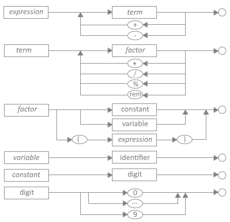
Syntax Analysis. Parsers perform two functions: (1) syntax analysis and (2) semantic analysis. The syntax of a programming language concerns the structure of its constructs. The syntax analyzer identifies sequences of symbols and validates their legality. In top-down recursive descent parsers, the syntax analyzer creates a tree-like intermediate representation that depicts the grammatical structure of the token stream. In top-down push-down parsers, the syntax analyzer creates stack entries. Since context-free grammars have inherent shortcomings, most notably their inability to describe certain interdependencies between different units in a program, Ada/PM employs both methods.
One important Ada/PM requirement is that its grammar must form unambiguous constructs. That is, every string generated by the grammar can only have one parse tree. This is because ambiguous constructs have the potential of providing different solutions to a parsing description. Figure 7 points out the difference between ambiguous and unambiguous syntactic constructs.
Figure 7. Syntax Constructs

index = value + rate * 10;    -- Ambiguous statement raises a warning
index = value + (rate * 10)-  -- Unambiguous statement that uses parentheses to disambiguate
Figure 7 shows that in the case where value = 100 and rate = 1000, then the ambiguous statement could give two different answers (either 11,000 or 10,100) depending on the order of the parse. If the warning pragma is turned off, then the statement will be processed from left to right.
Because Ada/PM does not invoke operator precedence like other programming languages, the compiler avoids this ambiguity by requiring parentheses to be used to indicate operator precedence. In the absence of parentheses, Ada/PM defaults to performing arithmetic operations from left to right. Therefore, without the use of parentheses, Ada/PM would add rate to value and then multiply the result by 100 giving an answer of 11,000. If this is not the desired solution, then the operands must be reordered, or parentheses must be used.
Derivations. The sequence of intermediary strings generated to expand the <start symbol> of the grammar to a desired string of terminals is called a derivation. The parser is responsible for representing derivations in the form of parse trees. Figure 8 shows the parse tree for the unambiguous statement index = value + (rate * 10).
Figure 8. Parse Tree for index = value + (rate * 10)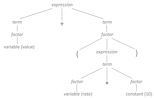
Another problem arises that can't be solved by Ada/PM's syntax analyzer. Figure 9 depicts a construct with perfectly formed syntax.
Figure 9. Acceptable Syntactic Definition

AnyVal : integer = "This is a string";  -- Perfectly formed syntax
Semantic Analysis. The semantics of a language specifies the meaning of its syntactic constructs. Figure 9 demonstrates a perfectly legal syntax, but it is not semantically correct. Although the assignment is correctly formed, a string of characters cannot be assigned to an integer variable. Identifying these kinds of errors is the job of the semantic analyzer.
Semantic analysis checks that the syntax portrays the correct meaning. In the previous example, the syntax is not semantically correct because the declaration is attempting to assign a string on the right side of the assignment symbol (i.e. =) to the integer variable "AnyVal" on the left side. A semantic error should be raised at this point. Semantic errors include type mismatch, anonymous types, undeclared variables, reserved word misuse, more than one declaration of a variable in the same scope, accessing out of scope variables, and actual argument and formal parameter mismatches.
There are three generally recognized types of parsers for grammars: (1) universal, (2) top-down, and (3) bottom-up. Although universal parsers are known for their ability to parse almost any kind of grammar, they are typically very inefficient. This often makes them less useful in compiler design; therefore, I will not discuss universal parsers.
A parser is considered top-down if it builds a parse tree corresponding to a token sequence by starting at the top of the tree and then expanding it downward to the leaves. Top-down parsing techniques are predictive in nature because they always predict the production that is to be matched before matching begins. A recursive descent parsing technique is a popular top-down approach.
Top-down parsers form the derivation of the input source file from the start symbol of the grammar and construct parse trees from that root at the top and proceed downwards through branches to subordinate constructs called leaves. Two approaches for top-down parsing are recognized: (1) recursive descent parsing and (2) predictive parsing.
Recursive Descent Parsing. Recursive descent parsing is a kind of top-down parsing consisting of a set of recursive routines that may require backtracking to create a proper parse tree. When a context-free grammar contains several alternative branches representing the next retrieved token, it must take a branch in order to check the validity of its choice. If the incorrect branch is taken, the subroutine must backtrack back up the tree and test another branch. This recursive process is time consuming for a compiler.
Predictive Parsing. A predictive parser is a top-down recursive parser that avoids backtracking by obtaining a lookahead character to check before making a branch decision. This is called top-down parsing without backtracking and it reduces the execution time to a linear function related to the length of the token being parsed.
Also, most top-down parsers scan a line to be parsed from left to right and make decisions on which rule (i.e. branch to take) based on the leftmost token on the line. This is referred to as an LL parser (left to right scan; leftmost derivation). When one lookahead character is used to avoid backtracking, the number one is placed inside parentheses like this: LL(1). LL(1) then means a top-down parser with left to right scanning using the leftmost derivation and 1 lookahead character.
Note that the drawbacks associated with top-down parsers include: (1) potential to enter into infinite loops, (2) potential to backtrack when no lookahead is employed, (3) near-impossibility of determining where errors occur, and (4) not all grammars lend themselves to top-down parsing. However, top-down predictive parsers have the advantage of being able to lend themselves to transition diagrams in a straightforward manner.
Bottom-up parsers build the structure of a parse tree by beginning at the bottom (leaves of the tree, which are terminal symbols) and determining the productions used to generate the leaves. The parser continues until it reaches the production used to expand the start symbol at the top of the tree.
Bottom-up parsing, also called shift-reduce parsing, is so called because the derivation tree is constructed from the bottom up. That is, they are constructed from the leaves of a tree and progress up to the root node. Almost all bottom-up parsers employ right derivation strategies, thus they are referred to as LR parsers. And in similar style to LL parsers, they can employ zero or more lookahead characters.
So, a LR(1) parser is a bottom-up parser with left to right scanning using the rightmost derivation and 1 lookahead character. If you recall that a leftmost derivation is one in which the leftmost nonterminal is expanded at each step; in the same manner, a rightmost derivation is one in which the rightmost nonterminal is expanded at each step.
There are three types of bottom-up parsers in general use today. They include: (1) Simple LR (SLR), Canonical LR (CLR), and Lookahead LR (LALR).
Most LR parsers are extremely difficult to implement and need specially formed grammars to work correctly. It is generally agreed that LALR(1) parsers are comparatively harder to implement, but more powerful than CLR(1) parsers. And, CLR(1) parsers are harder to implement than are SLR(1) parsers. Although LR parsers can detect syntactic errors a lot sooner in the parsing cycle and are generally faster than LL parsers, one of their principal drawbacks is that they are extremely difficult to handcraft. For this reason, specialized programs like Yacc and Bison have been developed.
When a compiler detects a syntax error, it usually attempts to continue with the parsing process so as to detect and record as many errors as possible.
Error handling is one of the most critical processes performed by a compiler. Generally, when the compiler detects a semantic error, it can continue compiling a program. When a syntactic error is detected, a serious condition exists that may force the compiler to stop processing the source code. However, error recovery is not easily accomplished. Since syntax errors potentially put the compiler into a state where continued compiling is not possible, it would make sense if the compiler could perform either error recovery or error repair. These two options play a vital role in the overall operation of a compiler.
Error Recovery. With error recovery, the compiler attempts to record the error and reset the parser so that the remaining program can be parsed. The problem with syntax errors is that they tend to cascade throughout the remaining code. This makes recovery extremely difficult at best and impossible in the worst-case scenario. Ada/PM has a built-in panic mode whereby the parser bails out when attempts at error recovery fail.
Error Repair. With error repair, sometimes called error correction, the compiler attempts to make repairs where it makes sense to do so. For instance, a simple typo or accidentally defining an improper type might be repairable whereas an incomplete sentence might not be repairable. One problem with self-repair is that a few false corrections may be made and never detected by the programmer. When Ada/PM makes a repair, it is reported so that the programmer becomes aware of the correction.
The biggest drawback to error repair is the amount of exacting extra code that must be added to a compiler with no guarantee of success. For this reason, Ada/PM's grammar is designed to make errors easily recognizable at the earliest possible opportunity and to provide minimal algorithms to affect repair. Ada/PM also has a built-in optimizer that determines when a point of diminishing return has occurred whereby any further effort at error recovery would not be worthwhile. At predetermined thresholds, the parser is designed to bail out with an appropriate error message. Figure 10 depicts a typical error report, which Ada/PM calls an exception.
Figure 10. Adagé Error Format

Syntax error 104 on Line 21: index integer;
                                  ^
                             Missing colon.
Ada/PM error reports provide line number, position, and error reference number. The error reference number allows programmers to cross reference errors in the Ada/PM Reference Manual. Note that exceptions incorporate more than just errors. Exceptions include warnings, cautions, and tips.
Most industrial-grade production compilers offered today produce intermediate code as part of the front-end output. Intermediate code is often stored in a tree-like format based on the needs of optimizers and code generators for various targeted processors. Other stored formats include the three-address statements. Intermediate code is also closer to the target machine than the source language, which makes it easier to generate actual code for the target processor and to optimize that code.
Intermediate Code (IC) represents an abstract form of machine code that models a generic processor. Most sources discuss two important properties of intermediate code. It is generally agreed that intermediate code (1) should be easy to produce and (2) easy to translate into assembly instructions for the target processor.
The purpose of intermediate code is to make a compiler more portable. That is, the intermediate code is easier to re-target for UNIX, Linux, and Windows operating systems, or even different or newer processors for that matter. Using intermediate code allows the details of the target processor and associated machine language to be confined to the backend of the compiler. In my opinion, intermediate code representations are also easier to optimize than actual assembly code.
 1.  ;-------------------------------------------------------
 2.  ; Listing 2. Intermediate Code Snippet
 3.  ; Pseudo Code: var index: integer = 50
 4.  ;              procedure Add_Int (x, y: int)
 5.  ;              begin
 6.  ;                x = x + y
 7.  ;              end procedure
 8.  ;
 9.  ;              Add_Int (index, 100)
10.  ;-------------------------------------------------------
11.  MEM index 8 BYTES  ; Set aside 8 bytes in memory
12.  ST @ADDR index 50  ; Store 50 at index location
13.  L1:                ; Begin procedure
14.  LD R1, STK1        ; Load address from stack location 1
15.  LD R2, [R1]        ; Load value located at address in R1
16.  LD R3, STK2        ; Load value from stack location 2
17.  ADD R3, R2         ; Add both registers
18.  ST [R1], R3        ; Store results at address in R1
19.  RET                ; Return to caller
20.  ;-------------------------------------------------------
Notice that the intermediate code in Listing 2 is quite different from code implemented by compiler programs like YACC. The intermediate code is based on the abstract syntax trees produced by the parser's syntax analyzer and validated by the semantic analyzer.
Almost all modern compilers perform some optimization. It should be noted that code optimization, as effective as it may be, rarely results in perfectly optimized code. There is always a point of diminishing return when optimization is involved.
The purpose of the code optimizer is to make the resulting code: (1) faster, (2) work on different processors, and (3) work on different operating systems. One drawback to the optimizing process is that a compiler can spend considerable time performing optimization. Code optimization almost always concerns trade-offs in time spent optimizing the code and any resulting speed-ups that may be realized. I highly recommend you download a copy of Agner Fog's Optimizing Subroutines in Assembly Language. It is free and comes in PDF format.
The initial versions of the Ada/PM compiler employ a post-code-peephole optimization technique. This optimization approach is performed on the actual assembly language code output by the code generator before it is submitted to the NASM assembler. Select assembly instructions are reviewed and optimized as necessary. This type of analysis is very limited in order to deal with the complexities of the x86-64 instruction set.
 1.  ;-------------------------------------------------------
 2.  ; Listing 3. Optimized Intermediate Code Stub
 3.  ; Pseudo Code: var index: integer = 50
 4.  ;              index = index + 100
 5.  ;-------------------------------------------------------
 6.  MEM index 8 BYTES  ; Set aside 8 bytes in memory
 7.  ST @ADDR index 50  ; Store 50 at index location
 8.  L1:                ; Begin procedure
 9.  LD R1, STK1        ; Load address from stack location 1
10.  LD R2, STK2        ; Load value from stack location 2
11.  ADD [R1], R2       ; Add value in R2 to address in R1
12.  RET                ; Return to caller
13.  ;-------------------------------------------------------
Notice that the optimizer eliminated two instructions and streamlined two others. The value on the stack at location STK2 is loaded directly into R2. The next instruction then adds the value in R2 directly to the memory location represented by "index". The address for "index" is contained in R1.
Code generation is the final phase of a compilation process. The major task of the code generator is to ensure that correct code is produced for the target microprocessor. The code generator uses the symbol table and intermediate code source in deciding which x86-64 instructions to use.
Machine-level code generation is the final phase of compiler operations. It usually consists of developing assembly language instructions to be passed to an assembler like NASM. Code generators use the intermediate code as input and translate those instructions into actual assembly code. Just note that perfect, or even good code generation is an extremely difficult endeavor. Building a code generator depends on intimate knowledge of assembly language instructions used by the processor and the syntax requirements of the assembler. For this reason, we narrowed our compiler to using the NASM assembler and targeted the Intel x86-64 architectural processor operating in 64-bit real mode on the Windows 64-bit Operating System.
;-----------------------------------------------
; Listing 4. Generated Code Snippet
; Pseudo Code: var index = 50
;              index = index + 100
;-----------------------------------------------
segment .data       ; Define data section
  index dq 50

segment .text       ; Define code section
  L1:               ; Begin procedure
  mov rax, 100
  add [index], rax
  xor rax, rax      ; Report no error condition
  ret               ; Return to caller
;-----------------------------------------------
Listing 4 shows the generated assembly language code that is fed directly to the Netwide Assembler program for conversion to machine code. The previous three examples are very simplistic views on how the intermediate code is optimized and then converted to assembly language code by the compiler. However, they do show the process used by the Ada/PM compiler. Intermediate code is used because it is easier to optimize, and it allows different back ends to be applied for different processors and operating systems.
The symbol table is a data structure used by compilers to store key information about identifiers recognized by the lexical analyzer during the scanning process. The information stored in the symbol table is used by the parser and code generator. The types of information stored include variables, procedures, functions, methods, tasks, constants, labels, structures, file identifiers, and other compiler generated data such as identifier attributes.
A symbol table is a construct for holding each identifier and its associated attributes. The purpose of the symbol table is to preserve data on named identifiers that may include storage allocation, data type, scope, value, and in the case of subroutines, their names and arguments.
The symbol table is also used to check for reserved words and to ensure in-scope names are used only once. Identifier names are entered into the data structure by the lexical analyzer. Later, during syntax analysis associated attributes are entered. During the semantic analysis and code generation phases, the symbol table is traversed. The semantic analyzer uses the symbol table to check that names are used consistently with their declared types. The code generator uses the symbol table to check on how much memory space is needed and what kind of run-time storage must be allocated to each name.
Symbol tables are typically implemented using a list, binary search tree, or hash table. The kind of structure used often depends on the number of anticipated names to be stored and the desired performance needed from the compiler. Our compiler uses IWBasic's dictionary data structure. This data structure is a hash table construct and represents one of the fastest methods for building and searching symbol tables.
Figure 11. Symbol Table Entries

NAME       TYPE       MODE    VALUE            VISIBLE  BYTES ARGUMENTS         RANGE
---------- ---------- ------- ---------------- -------- ----- ----------------- -----------------
$index     integer    in      50               true     8     n/a               int.min, int.max
$Add_Int   procedure  -       -                true     -     integer, integer
$value     float      in out  1.2345e+308      true     8     n/a               flt.min, flt.max
$big_str   string     in      "Assembly is..." true     128   n/a               128 bytes
$int_array array      in out  0                true     800   float             0, 99
Note that the contents of symbol tables can vary application to application and more than one symbol table may be used. Ada/PM builds three symbol tables. Appropriate data are extracted from these three tables and placed into a matrix that is saved and loaded into the runtime program each time it is executed.
No compiler is complete without a robust set of support tools. Requisite tools include: (1) preprocessor, (2) symbolic debugger, (3) disassembler, (4) validation suite, (5) text editor, (6) scanning program, (7) parsing program, (8) assembler program, and (9) linker.
The Ada/PM compiler comes with several essential tools including a symbolic debugger, validation suite, and standard library files. We will build the symbolic debugger, validation suite, scanning program, and parsing program as separate, time-consuming projects. A text editor and fully developed integrated development environment (IDE) are planned as future projects.
The assembler and linker are commercial products and must be carefully chosen before initiating compiler development. This is because assembler programs and linkers have distinct nuances, which must be built into the compiler. Additionally, a good disassembler should be downloaded and used to improve the overall effectiveness of Ada/PM executable programs.
IDEs are text editors that help programmers to get the correct programming syntax and then run the development tools to create executable program output files.
When the compiler has been fully tested, an accompanying Integrated Development Environment (IDE) will be developed as a separate project. The IDE will be a software application that provides comprehensive facilities to programmers for writing and debugging executable programs. It will consist of a source code editor, automated build tools, and a debugger. The Ada/PM IDE provides intelligent code completion and referential help. The Ada/PM IDE will be designed to maximize programmer productivity by providing tightly bound components with a similar user interface.
Features to be included in the Ada/PM IDE:
Figure 12. Ada/PM Integrated Development Environment
A preprocessor is a program that processes source files and provides a file that is used as input to another program such as a scanner program. The amount and type of preprocessing done depends on the nature of the preprocessor. Some preprocessors are only capable of performing relatively simple textual substitutions and macro expansions, while others have the power of full-fledged programming languages like the C preprocessor.
The initial version of the Ada/PM compiler does not provide a preprocessor. Preprocessing was left out on purpose because the use of preprocessor macros are inherently unsafe and often lead to unstable programs. However, the underlying NASM assembler contains many single- and multi-line macros that can be used when inline assembly code is incorporated in the main code. NASM's preprocessor capabilities provide for string substitution, text inclusion, and conditional compilation. Unfortunately, inline assembly code breaches Ada/PM's strict typing requirements and validation checking. A warning is raised stating that strict type checking, and validation are not being enforced. However, the use of contract constructs, discussed later, using aspect specifiers are implemented to mitigate typical issues concerning assembly language security breaches.
--------------------------------------------------------
-- Listing 5. NASM Preprocessor Macro Code
-- Package: standard.inc
-- Macro definitions for this library
--------------------------------------------------------
package Standard is
begin
  asm
    %ifndef standard_inc
    %define standard_inc
    extern _printf, __imp__printf

    segment .data
      TEXT.type EQU 0
      ...
      SCHAR.type EQU 31

    segment .text
      %imacro SCHAR 2  ; Define 8-bit signed integer
        %1 db %2
      %endmacro

      %imacro BCD 2    ; Define ten-byte BCD value
        %1 dt %2
      %endmacro
      ...
  end asm;
end Standard;
--------------------------------------------------------
A debugger is a software tool that lets programmers execute and validate their code statement by statement. Debuggers are generally tightly integrated into their associated compiler.
Ada/PM's debugger is a software tool built right into the compiler. It allows programs to be executed and validated instruction by instruction. The Ada/PM debugger is a symbolic debugger. This makes it an interactive, real-time tool that requires information from both the compiler and linker. For this reason, specific compiler options can be selected during program development that places debugging information in the compiled source program to aid in debugging.
Debugging features include the ability to examine and modify processor registers, data, and program memory; pause or stop program execution at defined program locations using breakpoints; single stepping one instruction at a time through the code; and tracing the history of executed code.
The Ada/PM debugger includes the following features:
Figure 13. Ada/PM Symbolic Debugger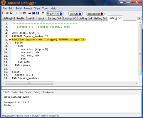
NOTE The Ada/PM IDE is under active development and will be offered in the future. It has not been finalized and fully tested.
The purpose of disassembly tools is to facilitate the understanding and validation of program source code, especially when the source code is unavailable.
There are several useful disassemblers available for Ada/PM programs. I recommend the freely available disassemblers offered by Ida Pro, OllyDbg, Agner Fog, and mrexodia. Hex-Rays charges for their latest software version of Ida Pro, but provides free 32-bit versions of previous releases. OllyDbg can be downloaded free of charge from Oleh Yuschuk's website. Agner Fog offers a free converter called objconv. This program is less capable than Ida Pro, but is easy to use and provides adequate disassembled listing information. Also, mrexodia offers x64dbg, which is very similar to Ida Pro. This is a freely available tool that is actively maintained. I use both Ida Pro and x64dbg to dump and disassemble object and executable files.
I use disassemblers to perform the following analyses:
Figure 14. Ida Pro Disassembler Program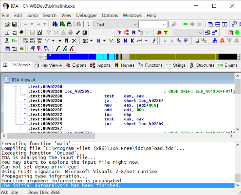
Note that Ida Pro is a recursive descent disassembler. Although there are numerous shortcomings related to the recursive descent approach, Ida Pro employs many heuristic techniques to provide additional code that may have gone missing from the recursive-descent process. Ida Pro is intelligent enough to distinguish data code from instructions. One of the more valuable features of Ida Pro is its ability to generate annotated comments about variables and subprograms. Ida Pro also provides a listing of machine-level code adjacent to each assembly instruction. This makes Ida Pro listings both powerful and easy to understand.
Validation and Verification tools are specifically designed to support the development of software used in high integrity applications. For instance, the Inspector program, part of the Ada/PM compiler, allows programmers to formally verify properties of their code such as information flow, dynamic errors, syntax correctness, code security, and functional properties.
One of the main tools in the Ada/PM arsenal is Inspector. It is a stand-alone program envisioned to help programmers validate and verify (V&V or ValVer) that their source code conforms to standard Ada/PM rules. Inspector is a valuable component program that has three fundamental functions:
Currently, the Ada/PM Inspector program is run from the command line in a console window. Inspector can be invoked simply by typing Inspector followed by the name of the file using full directory notation. However, I intend on integrating the Inspector program into the Ada/PM IDE as a selectable build option. Eventually, when all the functions of Inspector have been tested and are working properly, they will be designed right into the compiler so that source code validation and verification takes place during compilation.
Inspector is meant to reduce or eliminate the needed for extensive debugging. Debugging tends to be extremely problematic and may not even help in the discovery of the errors for which a programmer may be searching. Inspector is designed to find specific problems before they occur in a program so that debugging becomes unnecessary in terms of tracking down program errors.
The Ada/PM programming language with its core annotations ensures that a program does not contain certain errors related to the flow and type of static information. To check for dynamic error conditions, Inspector checks for proof annotations, which consist of pre- and post-conditions embedded in user comments. The advantage of Inspector is that it can conduct validation and verification on source code package specifications, even when the code is not ready for compilation.
Formal verification of Ada/PM code includes checks for possible divide by zero conditions, out of range variable assignments, incorrect type assignments, incorrect array indexing, arithmetic overflow situations, un-allowed aliasing, anonymous type usage, subprogram overloading, inappropriate pointer assignments, illegal data coercion and conversion, invalid return types, and infinite loop states.
Beyond its utility as a code checker, the aspect clauses inserted in the interface sections of packages provide programmers with additional information about how its subprograms are supposed to behave. For instance, consider the information given in Listing 6.
------------------------------------------------------
-- Listing 6. Typical Ada/PM Interface
-- No annotations appear in this interface version
------------------------------------------------------
interface Total_Cost is
  procedure Compute_Cost (x: in float);
end Total_Cost;
------------------------------------------------------
The interface shown in Listing 6 tells us very little about the procedure. All we know is that it takes a float value whose formal name is "x". It says nothing about what the procedure does or what "x" represents. Now, consider what happens when more descriptive parameters are used, and annotations are added as shown in Listing 7.
------------------------------------------------------------------------------------
-- Listing 7. Annotated Interface for Package Total_Cost
-- Aspect clauses are used by Inspector to check source code
------------------------------------------------------------------------------------
interface Total_Cost is
   global total: float                       -- Make global variables visible

  procedure Compute_Cost (price: in float);  -- Use more descriptive parameter name
    with global out => total                 -- Set total as write only
    pre in price => 0.0                      -- Ensure actual input is > 0.0
    post out total => 0.0                    -- Ensure actual output is > 0.0
end Total_Cost;
-----------------------------------------------------------------------------------
As shown in Listing 7, we now have a whole lot of useful information. For instance, we now know the following about the package:
Not only do we know more about what's going on with the procedure, the aspect clauses guide Inspector in making the following checks in the package body:
Note that formal verification of subprogram properties is based on contracts expressed as pre-conditions, post-conditions, type invariants and so on. Ada/PM annotations are only found in package specifications (interfaces). There are no annotations in package bodies unless refinement is required. The form for annotations lets the compiler treat them as human-readable comments but remain recognizable as annotations to the Inspector program. Since annotations are treated as comments by the compiler, they do not add to the size of programs. There are a few pre-defined aspect clauses in addition to global, pre, post, initializes, and derives that can be used to perform Ada/PM program code validation and verification.
Besides providing information to Inspector and increasing user insight, why bother with annotated comments anyway? The answer is that annotations provide aspect clauses that tell Inspector what checks are to be performed. Typical checks include data-flow analysis, initialization of variables, data dependencies of subprograms, and range and boundary conditions. Annotations do not add to the size of the final program because comments are not included. All Inspector checks are performed statically. Listing 8 displays both the interface and package body for the Total_Cost package.
-------------------------------------------------------------------------------
-- Listing 8. Package Specification without using Annotations
-- This version adds substantial code to perform dynamic checks
-------------------------------------------------------------------------------
with io;
interface Total_Cost is                     -- Interface to package body
  with global cost: float;                  -- Make global variables visible

  function Compute_Cost (price: float) return float;
    with global out total                   -- Set total as write only
    pre in price > 0.0                      -- Ensure actual input is > 0.0
    post total > 0.0                        -- Ensure actual output is > 0.0
end interface;

package Total_Cost is                       -- Package body
  cost: float;

  function Compute_Cost (price: float) return float is
    tax, total: float;
  begin
    tax = price * 0.05;
    total = price + tax;
    return total;
  end Compute_Cost;

begin
  cost = Compute_Cost (1250.90);
  io.put (cost);
end Total_Cost;
-------------------------------------------------------------------------------
In the previous listing, we included the package body. Package bodies normally are private, meaning other packages and subprograms that import their subprograms and variable only have visibility over the interface. From a user standpoint, annotations provide much needed information about how those subprograms work and what data are being passed to them.
Although Ada/PM provides a contract-based programming environment, it does not offer aspect-related specifications like the SPARK 2014 programming language. The reason for this decision is that aspect-type contracts add a whole new level of executable program code that greatly increases the complexity and size of both the compiler and user programs. For this reason, Ada/PM will use only annotated comments for now.
Lex and Flex are general-purpose scanner generators designed to be re-targetable and machine independent. Scanners, sometimes called tokenizers, are programs that recognize lexical patterns in text. Both produce tables that are used by driver routines to create complete scanner programs. Example 20 depicts a package specification containing Inspector annotations.
Lex, Flex, and ANTLR are scanner generators, which perform automatic lexical analysis on input source files. Scanning is accomplished based on information about the language in the form of regular expressions input by the programmer. Lex and Flex, originally designed for UNIX, output C/C++ objective files. These files are then fed to a parsing program (typically Yacc or Bison). Since our scanner is handcrafted, we do not use Lex and Flex in any of our projects.
The reasons we are not using either Lex, Flex, or ANTLR is because: (1) in my opinion, these programs have huge learning curves and (2) we want to understand how scanners work by building our own from the ground up. Just recognize that when you hear the terms Lex, Flex, and ANTLR we are talking about automated scanner generators.
Yacc is a look ahead left-to-right (LALR) parser generator, generating a parser, the part of a compiler that tries to make syntactic sense of the source code. It is based on an analytic grammar written in a notation like Backus–Naur Form (BNF). The GNU Bison is a general-purpose parser generator that converts an annotated context-free grammar into a deterministic LR or generalized LR (GLR) parser employing LALR(1) parser tables. In its current version, ANTLR 4 is a tool that translates grammar to a parser/lexer in Java (or another target language) and the runtime needed by the generated parsers/lexers.
Yacc, developed by AT&T, is a general-purpose program for generating LALR(1) parsers based on grammars written in Backus-Naur Form (BNF). Originally developed for Unix operating systems, current versions can be found for the Windows OS. GNU Bison and PCYacc are reimplementations of Yacc and purportedly offer improvements and additional features over Yacc.
Yacc, Bison, and ANTLR only build parsers based on context-free grammars input by programmers. Except for ANTLR, compilers still require lexical analyzers such as Lex or Flex to perform scanning functions. All parser generators have unique learning curves. Yacc and Bison require a C/C++ compiler, or in some cases a Java compiler, to create the parsing program. ANTLR can be implemented using Java, JavaScript, C++, C#, Python, Go, and Swift. Naturally, each program produces language-specific output files.
Another reasonable offering is the GOLD Parser. According to its developers, GOLD generates parsers that use Deterministic Finite Automatons (DFA) for the tokenizer and a LALR(1) for the state machine. Unlike other parser generators, GOLD does not require you to embed your grammar into your source code. It saves the parse tables into a separate file, which is loaded by the parser engine when run.
A recent addition to modern parser generators is ANTLR (ANother Tool for Language Recognition). It is used for reading, processing, executing, or translating structured text or binary files. From a formal language description called a grammar, ANTLR generates a parser that can build parse trees and generate tree walkers that can be used to access the nodes of those trees.
Again, since we are hand crafting our compiler, we do not use automated parser generators in any of our publications. Our purpose for building a compiler in the first place is three-fold: (1) specify a context-free grammar for our language, (2) write the algorithms necessary to implement a working parser, and (3) create symbol table structures to hold names and attributes. We always have the option of employing third-party parser generators later if we find we need more powerful tools.
When a source code file is created by the code generator of a compiler, it is assembled into an object file with an assembler program. Once the source file has been successfully assembled into an object file, it is linked using a linker program. When all the object files have been linked, an executable program file is created and ready to use.
Ada/PM employs the Netwide Assembler (NASM) program to translate the human-readable source code generated by the compiler's code generator into machine-level hexadecimal code instructions. These hex code instructions are output into an object file that can be linked together with other object files.
The job of a linker is to combine object modules saved in different files into a single executable program. Linkers also take care of memory allocation by assigning data and instructions to memory addresses in such a way that different modules do not overlap. Ada/PM uses the GoLink linker program to link object files into a single executable program file.
An assembler is a type of computer program that translates the output of the code generator from human-readable assembly language to machine-level hexadecimal format that can be executed by a microprocessor.
An assembler is a software program that interprets assembly language source files into machine-level language that can be executed by a computer. Assembler software allows program developers to access, operate, and manage computers at the hardware level.
Ada/PM uses the Netwide Assembler (NASM) as its underlying assembler program. NASM is an 80x64 assembler designed for portability and modularity. It supports a range of Windows compatible file formats including Win32 and Win64 object file formats. Its syntax is designed to be simple and easy to understand, like Intel's, but less complex. Most importantly, NASM supports all currently known x86 architectural extensions and provides powerful macro constructs.
Here is a list of NASM's key features:
GoLink is a free linker that takes COFF object and resource files and creates executable (EXE) or dynamic linked libraries (DLL). GoLink runs under 32-bit and 64-bit Windows operating systems. This is a full featured linker that keeps file size to a minimum. One notable feature of GoLink is that Lib files are not needed to identify what functions reside in linked DLLs. Instead GoLink looks inside the DLLs themselves to find the appropriate functions. GoLink also reports redundant program data and code.
A linker is a software program that combines object modules to form an executable program. Since Ada/PM allows you to write and compile separate modules in order to break up large programs into smaller pieces of manageable code, a program is needed to combine all these modules into one executable program. This is the job of the linker.
Another job of the linker is to replace symbolic addresses in program code with actual addresses. This is necessary even if only one module is being linked. Although there are many exceptional linkers to be found on the internet, I chose Jeremy Gordon's GoLink linker because of its features and that it works with Windows 64-bit Common Object File Format (COFF) source files, which are produced by the Ada/PM compiler.
Here is a short list of GoLink's salient features:
There are four parts to this book. Part I introduces the major concepts of a compiler and interpreter. Chapter 1 introduces the basic structure of a compiler. Chapter 2 develops an understanding of the scanner and lexical analysis. Chapter 3 introduces three utility programs and symbol table structures. Chapter 4 covers the parsing of expressions. Chapter 5 expands on expression parsing by discussing the parsing of statements. Chapter 6 provides coverage of declaration parsing. Chapter 7 focuses on parsing programs, procedures, and functions.
Part II includes chapters 8 through 11. Chapter 8 focuses on intermediate code representation. Chapter 9 shows how to interpret procedures, functions, and assignment statements while Chapter 10 covers interpretation of control statements. Chapter 11 demonstrates how to create and interpret a simple interactive debugger command language.
Part III includes chapters 12 through 15. Chapter 12 focuses on Intel x86-64 object code generation. Chapter 13 demonstrates how to compile procedures, functions, and assignment statements. Chapter 14 provides examples of how to compile control statements. Chapter 15 includes an overview of various advanced concepts relative to compile functionality including object code optimization and dead code elimination.
The Appendices make up the final part of the book. Appendix A contains the source listing of the Ada/PM interpreter. Appendix B contains the source listing of the Ada/PM compiler. Appendix C provides a definition of the Ada/PM programming language.
NOTICE Chapters and topics related to the Ada/PM Compiler Design & Development manual are subject to change as the project matures and advanced technologies are incorporated.
Page TopCopyright © PMzone Software. All rights reserved. Terms of Use